The purpose of the main turbine is to convert the thermal energy of the steam exiting the steam generators into mechanical energy to turn the main generator. Steam from the secondary side of the steam generators of a nuclear steam supply system enters the high-pressure turbine of the turbine-generator set exits to the moisture separator rebeaters, and then enters the low-pressure turbines. The steam rotates the shaft of the generator by rotating the blades of the turbine cylinders. The generator produces the electrical power of the power plant.
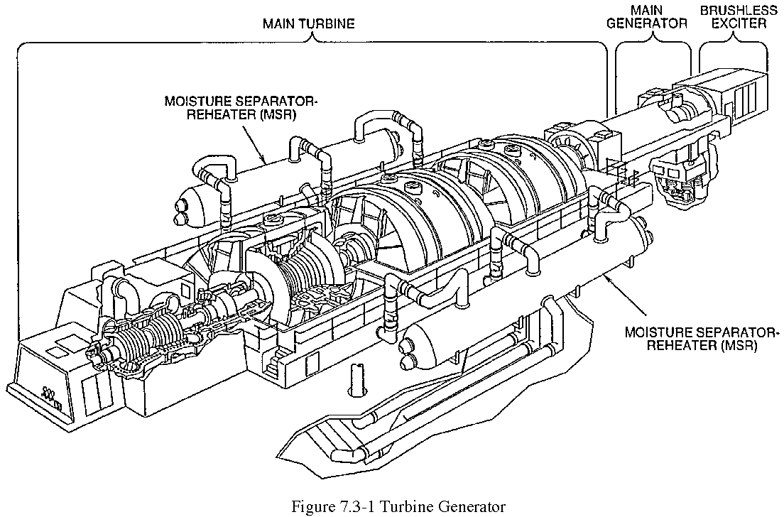
Westinghouse supplies nuclear turbine-generator systems over a load range of 600 megawatts electrical (MWe) to 1500 MWe in three- and four-cylinder configurations for any light water reactor. Described in this chapter is the four-cylinder, tandem-compound, six-flow, nuclear turbine-generator set (Figure 7.3-1) for a four-loop power plant. The turbine-generator can produce up to approximately 1500 MWe with 45-inch last row blades.
The typical main turbine (Figure 7.3-1) is a four-cylinder, 1800 revolutions per minute (rpm) unit with tandem-compound, six-flow exhaust and 45-inch last row blades. This configuration is used typically for ratings in the 1,100 to 1,500 MWe range.
The main turbine consists of one double-flow high pressure cylinder -in, tandem with three double-flow low pressure cylinders. Combination moisture separator reheaters (MSR) assemblies are provided between the high and low pressure turbines to dry and superheat the high-pressure turbine exhaust steam.
The high-pressure turbine is a double-flow element with an impulse stage followed by seven stages of reaction blading in each end of the cylinder. The pressure in the impulse stage (first stage turbine pressure - Pimp) is monitored and used in protection and control circuits as an indication of turbine load. The steam enters the high pressure turbine through two steam chests, one located on each side of the turbine. The steam passes into each steam chest through either of two throttle and governor valve sets. Once inside the high pressure turbine, the steam flows axially in both directions from the inlet chambers, through the impulse stage and reaction blading, to the six exhaust openings (three at each end), then through the cross-under piping to the moisture separator reheaters. Crossover pipes return the steam through either of six sets of reheat stop and intercept valves to the three low-pressure turbines (two sets of valves per low-pressure turbine).
Each low-pressure turbine is a double-flow cylinder employing eight stages of reaction blading. Dry, superheated steam from the MSRs enters each of the three low-pressure turbines through the reheat stop and intercept valves at the center of the blade path, travels axially in both directions through eight stages of blading, then exhausts downward to the condenser. Openings are provided in the high- and low-pressure cylinders through which steam may be extracted from certain stages of turbine blading. Extraction steam is used to preheat the main feedwater in the high-pressure and low-pressure feedwater heaters (Chapter 7.2) and reheat the steam as it passes through the MSRs.
Steam admission to the main turbine is controlled by positioning of the throttle and governor valves for the high pressure turbine and the reheat stop and intercept valves for the low pressure turbines. Each valve is controlled by the electrohydraulic control (EHC) system through an individually operated valve actuator. The throttle, reheat stop, and intercept valves are normally maintained full open during power operations with load on the turbine being controlled by the positioning of the governor valves by the EHC. All of the valves are automatically closed by the EHC on a turbine trip signal.
The high pressure turbine rotor is machined from an alloy steel forging and supported by two bearings. An auxiliary shaft is bolted to the governor end of the rotor and is used to drive the impeller of a shaft driven oil pump.
The low-pressure turbine rotors are integrally forged with the rotor body. The discs are then machined from the forging to their final configuration.
Flanged, rigid-type couplings are used to connect the rotors of the four turbines and the generator. The rotating element is supported by ten journal bearings and is located axially by a thrust bearing mounted at the governor end of the center low pressure turbine.
Low pressure turbine rotors are interchangeable because of tolerance control achieved in manufacturing. Therefore, spare rotors can be made available to reduce outage time.
The high pressure blade path consists of a double-flow impulse stage followed by seven stages of double-flow reaction blading. The impulse stage blades are integral with the shroud and machined from a solid block of high strength steel.
The low pressure turbine blade path consists of eight stages of double-flow reaction blading designed to accommodate high exhaust pressure operation. Highly effective interstage moisture removal at the extraction points results in reduced blade erosion and improved steam cycle efficiency.
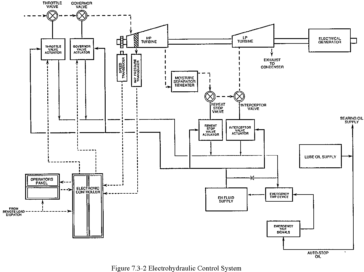
The turbine steam admission valves are opened by the high pressure hydraulic on the valves' actuators or operators. An electronic controller computes error signals comparing actual turbine speed and/or turbine load with reference (desired) values established by the operator. The resulting control signal is transmitted to the electrohydraulic fluid actuator on the turbine governor and throttle valves. The electrohydraulic fluid system provides the power for all turbine valve actuators and positions the governor and throttle valves in response to the electronic control signals from the controller.
The electrohydraulic control (EHC) system provides:
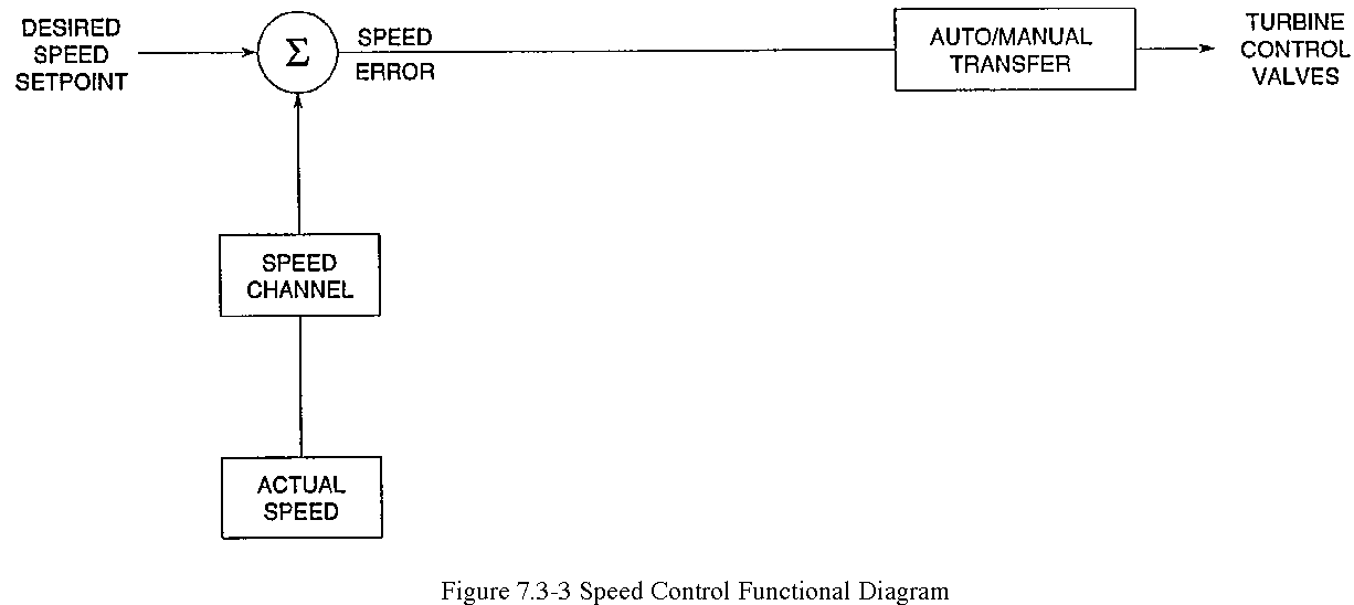
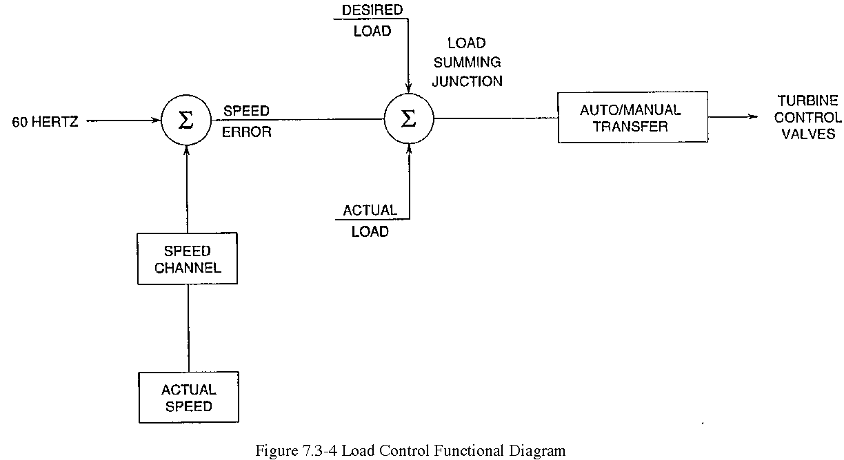
The control system operates in speed control mode or load control mode. "Speed control" (Figure 7.3-3) is used to bring the turbine from turning gear operation to synchronous speed. The error between actual and desired speed is used to position the turbine control valves to accelerate the turbine to the desired speed. The control system automatically switches to the "load control" mode (Figure 7.3-4) when a generator output breaker is closed. In load control, the error between actual turbine load and desired load with an input from the speed error channel are combined to operate the control valves.
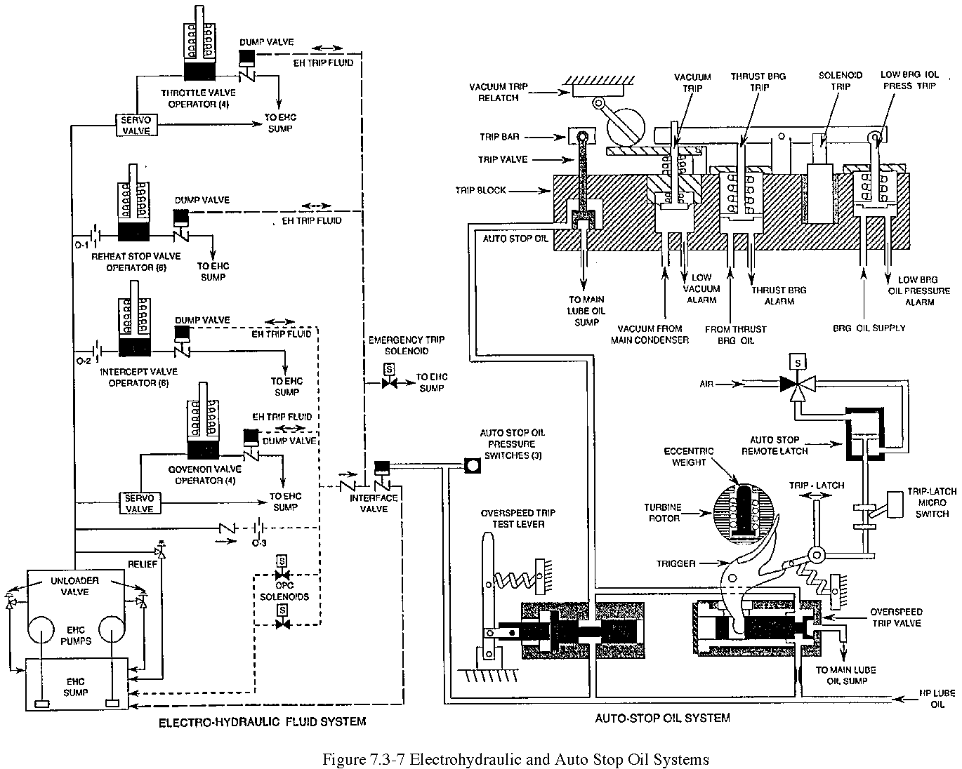
A mechanical-hydraulic turbine emergency trip system (Figure 7.3-7) is provided to trip the turbine when a problem is detected. This system, which is completely independent of the EHC, is called the auto stop oil system. The auto stop oil system uses oil from the turbine-generator lubricating system (Figure 7.3-2) to maintain the interface valve with the electrohydraulic fluid supply closed. Release (depressurization) of the auto stop oil by any of the turbine trip devices causes the interface valve to open and all high-pressure turbine and low-pressure turbine steam admission valves to close by dumping the electrohydraulic fluid from their actuators. Low auto-stop oil pressure and/or all turbine throttle valves closed signals are sent to the reactor protection system to indicate to the reactor protection system that the turbine has tripped. Under certain conditions, the reactor protection system will generate a reactor trip when a turbine trip has occurred.
The turbine is tripped when the emergency trip device opens the interface valve, thus closing all turbine valves by dumping the hydraulic fluid from their actuators. The following turbine protective devices will result in a turbine trip:
Turbine overspeed protection is provided by a mechanical overspeed trip mechanism and a redundant electrical overspeed trip system. Both systems ensure that the turbine does not exceed 120% of design speed. In addition, an overspeed protection controller causes electrohydraulic fluid from the governor and intercept valves to dump to the drain, sump, thereby closing the governor and intercepts valves at a preselected percent above rated speed to slow the speed of the turbine and attempt to prevent an overspeed trip. The governor and intercept valves reopen when, the overspeed condition clears. The electrical solenoid protective trip devices are all included on a mechanical trip block assembly which connects hydraulically to the auto stop oil system. Actuation of any one of these devices, therefore, causes the interface valve to open and turbine valve hydraulic fluid to be dumped to the drain sump.
The electrohydraulic control system will decrease turbine load to a preselected setpoint under certain abnormal plant conditions to maintain the plant within design conditions. These types of load reductions are called "runbacks." The following are several of the turbine runbacks that a plant may be provided with:
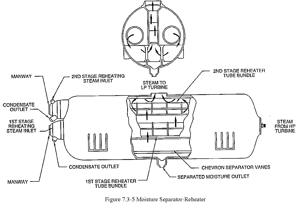
Typical combined moisture separator reheaters (Figure 7.3-5) between the high pressure and low, pressure turbines remove the moisture in the steam exhausting from the high pressure turbine and reheat the steam to over 100°F of superheat. The wet steam enters the moisture removal section and rises through the chevron-type moisture separators where the water is removed and drained to the feedwater system. The dried steam then passes through the reheater section where it is reheated by the highest pressure extraction steam and by main steam withdrawn before the throttle valves. The heating steam is condensed in the tubes and is returned via the heater drain system to the feedwater system. The reheated steam goes to the low pressure turbines and to the main feedwater pump turbines.
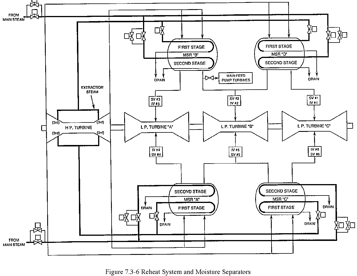
The first stage reheater has a built-in pressure control, because the steam is taken from the high pressure turbine third stage extraction (Figure 7.3-6). As turbine loading increases, the extraction pressure increases proportionally and flow through the reheater tubes increases.
The second stage reheater steam is supplied by the main steam bypass header. Since this steam is high pressure, high temperature steam, a separate control system is provided to throttle steam pressure and flow. This throttling will control the hot reheat steam temperature increase in the moisture separator reheaters.
The main turbine converts thermal energy of the main steam into mechanical (rotational) energy of the generator rotor resulting in the generation of electrical energy. Extraction steam from the high and low pressure turbines is used for feedwater preheating. The moisture separator reheaters dry and superheat the exhaust steam from the high pressure turbine before the steam enters the low pressure turbines. The turbine electrohydraulic control system provides both speed control and load control of the turbine. On a turbine trip, the turbine system sends "low auto-stop oil pressure" and "all turbine throttle valves closed" signals to the reactor protection system.